Matt’s back in town! (with pictures of black silicon…)


I’m back in Richmond now, having just returned from a year-long research sabbatical in France working on a new project involving “Black Silicon.” When a smooth surface of pure silicon is subjected to plasma etching under certain special conditions, it can spontaneously form a dense forest of microscopic spikes and holes, typically a few hundred nanometers across and a handful of microns high.  As a result of this extreme roughness, light which is incident on the surface becomes trapped, and is eventually absorbed by the material, making it appear black to the naked eye.  Beyond the many interesting physics questions this material raises (How does this happen?  What determines the length scale?) this material has several potential applications, including the possibility for more efficient solar cells.

A scanning electron microscope image of black silicon

My work in France was at ESIEE Paris, an engineering school in the eastern suburbs of Paris.  I will continue to work on this project here at Richmond, collaborating with my French colleagues remotely.   Although we don’t have the plasma etching equipment here, we do have access to microscopy and analysis tools.   I also expect to return to Paris for several weeks at a time during the summers.

Review of Global Specialties PB-503 (do not buy)

I normally don’t review products here, but I’ve had a recent experience with the Global Specialties PB-503 that’s left a particularly bad taste in my mouth.  Since many of the vendors who sell it don’t post product reviews, I’ll write mine here.

On the plus side, this unit is a compact and convenient way to combine several DC power supplies and a function generator with a conveniently large breadboard area.  The design is well-suited to my introductory electronics course, for instance.

However, I have been unimpressed with the durability of these units.  Used in a classroom setting, I have had to repair several of these that failed over a semester. (By contrast, the multimeters I have used in the classroom have gone through many fuses, but have never been damaged.)  Repairs have included blown regulators in the DC power supplies and damaged voltage adjustment knobs (trim pots). Another had a bad solder joint.

Worse yet, these units have a known design flaw which the company seems uninterested in addressing.  The TTL output on the function generator does not work when the unit is in sine wave or triangle wave mode (which, after all, is when the TTL output is actually needed).  According to Global Specialties, this is due to a forced redesign of the unit when one of their parts became obsolete and unavailable.  I notified Global Specialties of the TTL issue in January 2010.  Initially, they assured me they would inform me of a fix for this problem within a few weeks.  Almost one year later, I have heard no news of a resolution to this design issue, and the company has not responded to my latest inquiries.

As it stands, this product does not do what it is supposed to do; if the company has plans to fix it, they have kept those plans from me.  I recommend against purchasing these units until this defect is addressed.

Vampire power: unplug the cable box!

The other day I became curious about how much power was being used by various electrical appliances in my house.  In particular, I was curious about “standby power” or “vampire power”: the electrical power drawn by devices when they are idle or even completely turned off.  So I stole borrowed a digital multimeter from work, connected it to an extension cord (had to cut open the cord), and voila–my own power meter!  To get the power usage in Watts, I measure AC current (amps, rms) and multiply by 120 volts.

The results surprised me!

First, the good news: the little power supply that I use to recharge my cell phone is actually quite efficient.  With no phone plugged into it, it draws only 0.0009 amps, for a power consumption of about 0.1 Watt.  At 10 cents per kilowatt-hour, that works out to about 10 cents per year.  I still unplug it when not in use, just out of habit, but leaving it plugged in clearly wouldn’t ruin either me or our planet.

Next, the bad news.   Many other power bricks were very inefficient, drawing 4 to 6 Watts even when hooked up to no load!  Other appliances clearly have similarly inefficient power supplies inside them, like my Braun coffee maker, which draws 3.5 Watts even when it’s turned off–all to run a stupid little LCD clock which I’ve never even bothered to set to the correct time.   Other losers were a boom box (6.8 watts when off) and a pair of computer speakers (7.9 watts when off).

Why are some of these so bad?  The answer, unfortunately, seems to be just bad design.  Old style power supplies often use transformers to step down the voltage from the 120 volts in a standard outlet to the handful of volts needed for the appliance.  These are the large, heavy black bricks that often feel warm to the touch when they are plugged in.  By contrast, the small power brick for my cell phone feels very light; it uses silicon-based electronics instead of the heavy iron-core transformer, and is much more efficient.  When the phone isn’t plugged in, the power supply doesn’t feel warm at all.

But the single worst offender was my cable box, made by Motorola and supplied to me by Comcast.  When it’s on, it draws 35 Watts.  But when it’s off, it still draws 34.5 watts! That’s costing me an extra $30 per year, for absolutely no benefit to me.  That’s  unconscionable!

The solution is simple: I have now put several of the worst offending devices on power strips with off switches.  Now when they’re off, they’re really off.  🙂  With a small amount of effort on my part, I should easily be able to save about $70 per year, which of course also reduces my carbon footprint and is generally good for the planet.

Do you have a story or question about “vampire power” you’d like to share?  Leave a comment and let me know.

Bad wiring in my house!

I was installing a ceiling fan in a bedroom in my house last weekend when I found that my home was badly miswired by the original builders.  The current wiring works, but is unsafe and clearly in violation of the national electric code.  (The home was built in 1995, when the builders REALLY should have known better.)  This turned out to be a nice circuits example for my intro physics class, so I thought I’d also post it here as an example of stuff you can learn in school that’s actually practical in real life.

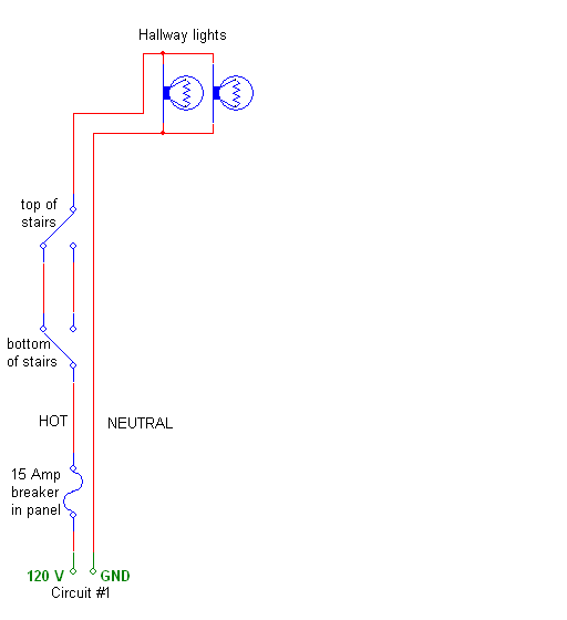
The issue is the wiring of some hallway lights which are controlled by two switches at the top and bottom of the staircase.  The picture below shows how it’s supposed to be wired, using two “three-way switches.”  (Confusingly, they’re apparently called “two-way switches” in the UK.)  Note that three separate wires (as in 3-wire cable) are required between the two switches.
bad_wiring1b.gif

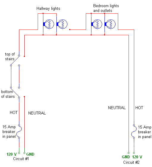
What happened in my house is this: the electrical contractors apparently ran out of 3-wire cable, and instead ran only 2-wire cable between the two switches.  This left them with no neutral wire to complete the circuit from the hallway lights.  Instead, they ran a cable to the bedroom, and connected to a neutral from a completely different branch circuit.  The wiring they did is shown below:
bad_wiring2b.gif

Here’s a quick quiz: what’s wrong with what they did?

Actually, there are three things wrong with it:

  1. In general, you want the supply and return current paths of a circuit to be near each other.  Big open loops in a circuit path tend to cause interference, degrading circuit performance.  (In some cases, they can also lead to inductive heating of metal structures near the wires, though not here.)  But this is the least of the problems.
  2. A much more serious problem is that the neutral wire in circuit #2 (for the bedroom) gets more current than it’s designed for.  The wires in circuit #2 are designed to handle only 15 Amps; any more, and the circuit breaker is supposed to shut the circuit off.  But in the diagram above, if the other lights and outlets in the bedroom draw 14 Amps through the breaker, and the hallway lights draw 2 Amps, then the neutral (return) wire for Circuit #2 carries 16 Amps, which is above its limit.  That’s a fire hazard.
  3. Another serious problem with this scheme is that a person working on circuit #2 (say, me, installing a ceiling fan) would typically turn off the breaker for circuit #2 and assume that he is safe.  But in fact, the neutral wire in this circuit still carries current from the hallway lights.  Breaking the neutral wire and touching it could lead to a nasty shock.  That’s how I found out something was wrong with my house: my hand brushed against a neutral wire and I got zapped.  I was uninjured, but this is serious: people have died because of this.

Now the really technical part:

I’m not a licensed electrician, but I believe this work is in violation of the National Electric Code, also known as NFPA 70.  In the situation above, the possibility of overcurrent in the neutral wire (grounded conductor) of circuit #2 appears to violate article 210.20.

Interestingly, I actually have two different places in my house that suffer from this defect.  One is exactly as I described above; the second is a little more subtle, because the two circuits are actually on different phases.  If the two hot wires (ungrounded conductors) are 180 degrees out of phase, the current in the shared neutral wire is actually the difference between the two currents, avoiding the overcurrent situation.  Bizarrely, I believe this makes the out-of-phase wiring scheme technically legal under older (pre 2005) versions of the code, when my house was built.  I think the two circuits would fall under the category of “multiwire branch circuits,” defined in article 100 and governed by article 210.4  (also known as “edison circuits” or “shared neutral circuits” or “common neutral circuits”).  Fortunately, this section of the code has been modified, and the newest version (2008) includes provisions in articles 210.4(B) and 210.7(B) that the two branch circuits must be equipped with a means to disconnect them simultaneously, such as a double pole breaker with a common trip tie in the panel box.  This prevents someone from disconnecting only one of the two circuits and mistakenly believing the circuit is safe to touch.  In my opinion, this update to the code is long overdue.

A quick note of clarification: although the preferred method of wiring a three way switch is to run a neutral wire from the same feed as the hot wire (using three-wire cable between the switches), there’s nothing sacred about that arrangement.  As long as the neutral wire coming from the lights is eventually connected back to the same branch circuit that the hot wire came from, there is no safety issue, though wrongness aspect #1 above still applies.  Three-wire cable is more expensive than two-wire cable, and two-wire cable can be safely used between three way switches, provided that the wire with white insulation is permanently reidentified by color as an ungrounded conductor, consistent with article 200.7(C)(1) and 200.7(C)(2).  (Were the white wires in my house between the two switches reidentified?  Of course not.)